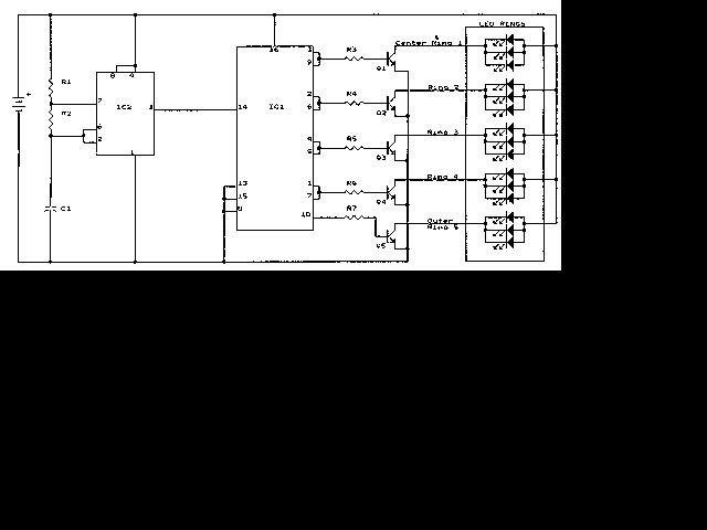
Here is the schematic, PC board pattern, and parts placement for a "Fantastic Atom Expander". This circuit produces an "exploding atom" effect using 98 LEDs.

PC Board Layout
Parts Placement
C1____________.1uf Mylar Capacitor
IC1____________4017 IC
IC2____________555 Timer IC
L1-L98_________Jumbo LED (any colour but blue)
Q1-Q5_________2N3904 NPN Transistor
R1_____________4.7k Resistor
R2_____________680k Resistor
R3-R7__________470 Ohm Resistor
MISC.__________PC Board, 9V Battery Snap, IC Sockets
1. The LEDs can be any colour but blue. For a very interesting effect, make one ring red, the next one green, the next one orange, then yellow, etc.
2. The transistors can be most any inexpensive NPN transistor (2N2222, PN2222A, Etc.).
3. For a very interesting (and expensive!) effect, replace the 2N3904's with 2N3055 power transistors on heatsinks and use 12 V 500ma incandescent bulbs instead of LEDs.